您的位置:首页 > 产品展示 > 射频微波/EMC测试设备 > Schwarzbeck
Radiating Loops
|
|
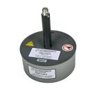
The magnetic, handheld coil FESP 5133 was designed to generate defined magnetic field strength in the audio frequency range up to 3 MHz. The main application is immunity testing against magnetic fields according to VG 95377 Part 13 and many others. Depending on the current source characteristics magnetic fields up to 400 A/m can be generated for a short time. There are further rings available on request in order to provide a certain scaling between coil current and magnetic field strength (e.g. 1 Amp coil current = 10 A/m field strength).
Application as magnetic field probe: The FESP 5133-9 can also be used to measure existing magnetic fields. The open circuit output voltage is directly proportional to the magnetic field strength (at fixed frequency) or directly proportional to frequency (at constant magnetic field strength).
|
|||||||||||||||||||||||||||||||||||||||||||||||||||||||||
|
|
The magnetic, handheld coil FESP 5132 was designed to generate defined magnetic fieldstrength in the audio frequency range up to 100 kHz. The main application is immunity testing against magnetic fields according to EN 55103 and MIL-STD-461 E. Depending on the current source characteristics magnetic fields up to 1500 A/m can be generated for a short time. The generated magnetic fieldstrength is proportional to the coil current. A distance ring allows a precise spacing of 50 mm between coil and EUT surface. Other distance rings can be used to scale the current-fieldstrength ratio. The highest fieldstrength levels can be achieved using the shortest ring. There are further rings available on request in order to provide a certain scaling between coil current and magnetic fieldstrength (e.g. 1 Amp coil current = 100 Amp/m fieldstrength).
Application as magnetic field probe: The FESP 5132 can also be used to measure existing magnetic fields. The open circuit output voltage is directly proportional to the magnetic fieldstrength (at fixed frequency) or directly proportional to frequency (at constant magnetic fieldstrength).
Option: Option LoopHolder50: Calibration fixture to hold FESP 5134-40 in FESP 5132 in a distance of 50 mm acc. MIL461E figure RS101-3.
|
||||||||||||||||||||||||||||||||||||||||||||||||
|
|
The handheld coil FESP 5133-1330 was designed for immunity testing against magnetic fields up to approx. 20 kHz. The coil has 225 turns of Cu-wire on 15 layers. There are spacers to provide a constant distance of 50 mm between coil center and EuT-surface. The generated magnetic fieldstrength is direct proportional to the coil current. Typical Applications are Immunity Tests according to the Measuring Method SF 01 G acc. to VG 95377 standard.
|
||||||||||||||||||||||||||||||||||||||||||||||||||||||||||||
|
|
The magnetic loop FESP 5135 was designed to generate magnetic fields in the frequency range up to 300 kHz. The FESP 5135 is esp ecially used for magnetic immunity testing for large EuT which does not fit between Helmholtz coils. The FESP 5135 is equipped with spacers in order to achieve good repeatability of test results without using additional length measuring equipment. The magn etic fieldstrength generated by the coil is strictly proportional to the coil current, therefore a current measurement ca be used to determine the actual fieldstrength.
|
||||||||||||||||||||||||||||||||||||||||||||||||||||||
|
|
The magnetic, handheld coil FESP 5133 was designed to generate defined magnetic field strength in the audio frequency range up to 100 kHz. The main application is immunity testing against magnetic fields according to e.g. (of professional studio equipment acc. to EN 55103), MIL-STD 461, VG 95377 part 13) and many others). Depending on the current source characteristics magnetic fields up to 1000 A/m can be generated for a short time. The generated magnetic field strength is proportional to the coil current. Two different distance rings (50 mm and 100 mm separation) are supplied to ensure a well defined spacing between the coil plane and the EuT-surface. The highest field strength levels can be achieved using the shortest ring. There are further rings available on request in order to provide a certain scaling between coil current and magnetic field strength (e.g. 1 Amp coil current = 100 Amp/m field strength)
Application as magnetic field probe: The FESP 5133 can also be used to measure existing magnetic fields. The open circuit output voltage is directly proportional to the magnetic field strength (at fixed frequency) or directly proportional to frequency (at constant magnetic field strength).
|
|||||||||||||||||||||||||||||||||||||||||||||||||||||||||||||||||||||
|
|
The square induction coil FESP 5210-1 is used to generate magnetic fields for immunity testing according to IEC 61000-4-8, IEC 61000-4-9 and IEC 61000-4-10. The edge length of the square shaped coil is 1 m. The coil comes with wing terminals, which allow a versatile and simple connection to the current source.
Operation as Helmholtz Coil: Two square induction coil FESP 5210-1 can be combined to form a Helmholtz coil pair. The main advantages of a Helmholtz coil pair is an increase of fieldstrength and a significant improve- ment of field uniformity. For this purpose the coil planes are aligned in parallel. Electrically the coils have to be wired in series, keeping in mind that the current through the coils must flow in the same direction. This is very important to obtain the wanted addition of both fieldstrength contributions in the volume between the coils.
|


